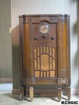
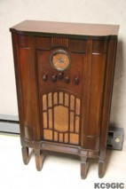
"Before" "After"
Brand: Radio Corporation of America
Year of Manufacture: 1934 Frequency Range(s): 550-1600 Kc 1.8-5.5 Mc, 5.5-18 Mc
Tube Lineup: 80 Rectifier, 41 Output, 6B7 2nd Det, 6D6 I.F., 6A7 Det/Osc, 6D6 R.F.
Schematic: Available here, courtesy of Nostalgia Air. Riders 5-65
Tube Lineup: 80 Rectifier, 41 Output, 6B7 2nd Det, 6D6 I.F., 6A7 Det/Osc, 6D6 R.F.
Schematic: Available here, courtesy of Nostalgia Air. Riders 5-65
Disassembly and Inspection
This radio came into my possession in early October of 2005. I had spotted this radio several months before in a local antique shop, but when I looked for a price, the radio was marked as sold. Turns out a close family friend bought this radio as a college pre-graduation gift for me. The radio sat in storage for several months until April 2006, when I decided to tackle this project. I set my goal at less than two months to completely restore this one, since projects had been going very slow that year.
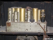
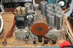
The chassis was covered in a thick layer of dust, with a layer of corrosion underneath that. Despite the worn appearance, the cabinet was in good condition, and the original finish was salvageable. Below photos: The chassis before cleaning.
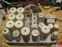
Chassis Restoration
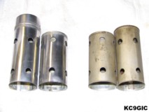
The first task was to clean the loose material from the chassis. A paintbrush and a vacuum were used to remove the dust and debris. This revealed a yellow colored chassis, which many large rusted areas. The tube shields and coil covers were then removed for cleaning. Brasso, blue shop rags, and a ton of elbow grease were required to clean these. Below center: The major difference that a cleaning made to the tube shields.
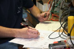
My best solution for repairing the electronics on radios consists of three main steps: #1 - Replace all electrolytic and paper capacitors with modern equivalents, #2 - replace the original cloth covered line cord with a modern reproduction cloth covered cord, and #3 - throughly clean the controls with contact cleaner, and lube all moving parts. This proved to be a small challenge. Almost all of the paper capacitors were original, and none of them were marked with any sort of values, just some sort of part number that I could not find listed anywhere. My only option was to obtain a good quality schematic so the circuits could be traced out, the part parts identified. A schematic was purchased from Justradios.com.
To help keep the chassis looking original, the replacement polyester film capacitors were installed inside of the original paper capacitor shells. The old capacitors were heated until the wax became soft, the old guts were removed, replacements were glued in place with hot glue, and brown wax was used to seal the ends. I didn't feel like going through the trouble of trying to hide the electrolytic capacitors, so the new ones were simply installed on a small terminal strip below the chassis. Reproduction cloth covered wire and power cord from RadioDaze was used to replace the line cord and several other damaged wires. To protect the radio if something should ever short out, a in-line fuse holder was installed fusing the primary to the transformer. The power consumption on this model is only 85 Watts, which using Ohms Law is only around 0.7 amps, so a 250V, 1 Amp fuse was used. Below left: Identifying the capacitors using a schematic, Right: The restored chassis with restuff capacitors.
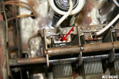
After cleaning the controls, it was time to test out the radio. Everything seemed to power up just fine. With a little bit of tinkering, and the connection of a long wire antenna, several local stations could be received, but there was a problem. A problem that I absolutely dreaded having to deal with. Even though the radio worked at times, the slightest vibration would cause it to go completely silent, or make loud popping sounds. There was an intermittent connection somewhere. My first suspicion was the tuning capacitor, since conductive dirt inside the plates can cause trouble. This part was cleaned very well, taking care to clean the metal brushes that make contact with the rotor. This had no effect on the bad performance. Next was checking over my work, and resoldering every solder joint I could see. No Change! After several hours, I was about to give up for a while, when I spotted one last solder joint on top of the tuning capacitor. The joint was heated up, new solder was added, and the problem went away completely! The old solder joint must have cracked sometime over the years. Below center: The suspected bad solder joint.
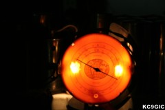
The
dial on this radio is lighted using two small 6 volt lamps with screw
in bases. When powered up in the dark, the dial looked sort of rough.
The foggy plastic pieces that mount in between the lamps and dial had
holes burnt in them, causing the light o be much brighter where the
lamps were, as seen in the below left photo. To remedy this, I made
some replacement reflectors from some plastic cut from a water
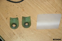
bottle. Below left: The dial with
bad refectors, Right: The burnt up reflectors.
With
the radio working rather well, I proceeded to reinstall the
chassis into the recently refinished cabinet. Everything was put back
together and it was time to fire it up. To my disappointment, the
intermittent connection was back, and just as bad as before. So once
again, the radio was disassembled. This time I re-rechecked my work,
tightened the contacts on the tube sockets, and resoldered many of the
joints. Tapping the tuning capacitor with a plastic stick would cause
the noise, so my problem must be there. The only part that had not been
cleaned or resoldered at this point were the metal rivets that connect
different terminals and lugs to the capacitor assembly. I heated these
up with my soldering iron, and bonded the rivets to the metal with
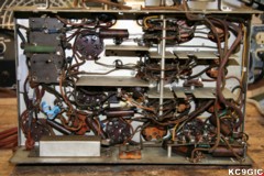
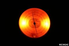
solder. This seemed to finally fix the problem. Below left: The dial with the new
reflectors installed, Right: The completed chassis.
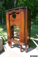
As seen in the "Before" photo, the cabinet had many chips, scratches, and sections of the original finish were gone. To get a good idea of the condition of the original finish, the whole cabinet had to be throughly cleaned. Using some 3M brand scrubbing pads, rubber gloves, and mineral spirits, the whole thing was scrubbed down to remove over 70 years worth of dirt. The top was in rough condition, which many deep scratches and discolored spots, but the rest of the cabinet looked salvageable.
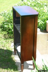
To blend in the numerous nicks and scratches, I wiped down the cabinet in small sections at a time with special walnut colored stain,. After a minuet or so the remaining stain was wiped off. This worked very well at blending in the bad spots. The top didn't look so great, so it had to be refinished. Using lacquer thinner, rubber gloves, and scrubbing pads, the finish on the top was stripped off. I used some Mohawk brand toners to match the color of the top with the rest of the cabinet, and then applied several coats of Deft brand semi gloss lacquer. The rest of the cabinet was then coated with several coats of semi gloss lacquer. Below: The completed cabinet.
Cabinet Restoration
As seen in the "Before" photo, the cabinet had many chips, scratches, and sections of the original finish were gone. To get a good idea of the condition of the original finish, the whole cabinet had to be throughly cleaned. Using some 3M brand scrubbing pads, rubber gloves, and mineral spirits, the whole thing was scrubbed down to remove over 70 years worth of dirt. The top was in rough condition, which many deep scratches and discolored spots, but the rest of the cabinet looked salvageable.
To blend in the numerous nicks and scratches, I wiped down the cabinet in small sections at a time with special walnut colored stain,. After a minuet or so the remaining stain was wiped off. This worked very well at blending in the bad spots. The top didn't look so great, so it had to be refinished. Using lacquer thinner, rubber gloves, and scrubbing pads, the finish on the top was stripped off. I used some Mohawk brand toners to match the color of the top with the rest of the cabinet, and then applied several coats of Deft brand semi gloss lacquer. The rest of the cabinet was then coated with several coats of semi gloss lacquer. Below: The completed cabinet.
Final Thoughts
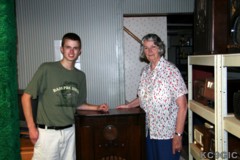
From start to finish (April - June 22nd 2006 ) this project took almost two months. I initially set my goal at one month, so I could show off my work at a party which family and friends would be attending. This was a rather easy restoration, given the size and condition of the radio. Cost is estimated at around $40.00, and the purchase price was nothing since this was a gift. Below: Me and my friend Marion in May 2006 (The person who gave me the radio).