Brand: Sears Silvertone Year of Manufacture: 1936 Frequency Range(s): 550- 1600 Kc, 6 - 17Mc
Tube Lineup: 1G1 Ballast, 950 Output, 1B5 AVC/Det/2nd A.F., 1A4 A.F., 1C6 Osc/Transl.
Schematic: Available here, courtesy of Nostalgia Air. Riders 8-5
Tube Lineup: 1G1 Ballast, 950 Output, 1B5 AVC/Det/2nd A.F., 1A4 A.F., 1C6 Osc/Transl.
Schematic: Available here, courtesy of Nostalgia Air. Riders 8-5
Preliminary Inspection
My
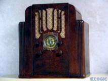
first purchase of a radio from eBay, in early December 2004. Quite
often, tombstone radios like this one can fetch some big
bucks, but being a battery radio, the price on this one was fairly low
as compared to others. The condition as described by the seller, which
was pretty rough, also contributed to the low price. My only
major concern was shipment of the
radio, but luckily the seller did a great packing job and the radio
arrived in good condition with no shipping damage.
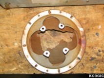
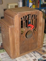
The condition was rather shabby when it finally arrived. The grill cloth and finish on the cabinet are not original. The speaker is missing parts, including the output transformer, magnet, and voice coil. The speaker cone is still there, but badly damaged. The cord that went to the battery is cut at the chassis, along with many other wires.
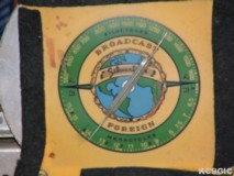
At first inspection, I could find no identification markings of any kind other than brand, so I posted a link to this page on the rec.antiques.radio+phono and received several replies that helped me narrow this radio down to a few possible models which use this same chassis. Later on, when doing some cabinet work,the model number was found written in white chalk inside of the cabinet. Below Left: The dial covered in dirt and stains, Right: The what was left of the speaker.
Back to Homepage
© Copyright 2005 "Jeremy's Antique Radios"
The condition was rather shabby when it finally arrived. The grill cloth and finish on the cabinet are not original. The speaker is missing parts, including the output transformer, magnet, and voice coil. The speaker cone is still there, but badly damaged. The cord that went to the battery is cut at the chassis, along with many other wires.
At first inspection, I could find no identification markings of any kind other than brand, so I posted a link to this page on the rec.antiques.radio+phono and received several replies that helped me narrow this radio down to a few possible models which use this same chassis. Later on, when doing some cabinet work,the model number was found written in white chalk inside of the cabinet. Below Left: The dial covered in dirt and stains, Right: The what was left of the speaker.
Electronic Restoration
Restoration
of the electronics began in late December of 2004. After
acquiring a schematic, the capacitors were confirmed as being
mostly original, and of the correct values. The first repairs consisted
of removing capacitors and replacing them with test leads with
alligator
clips on
both ends, all while taking many notes to minimize screw- ups in the
future. After removal, the replacement capacitors will be installed
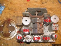
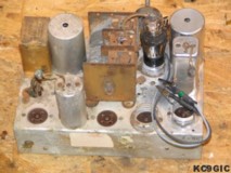
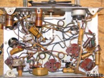
inside of the originals to preserve the appearance of the chassis. Below Left: A photo of the chassis marking
tubes and cut wires used in identifying the model, Right: The chassis
shortly after restoration began.
The
caps were then heated in a metal pan, and
the capacitors were gutted and wiped clean.
After the paper shells were clean, new polyester film capacitors of the
same value were placed inside the hollow tubes, longer leads soldered
onto
them, and they were sealed with hot glue. Some of the old
wax was then reheated,
and used to seal the ends to cover up the foggy white color of hot
glue.
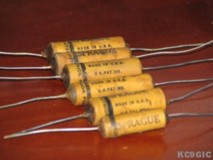
Below Left: the restuffed capacitors
ready to install, Right: the
chassis after being recapped.
By
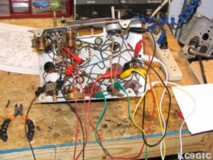
mid January 2005 the upper chassis rewire was pretty much finished.
The lower left photo shows the right half of the chassis has already
been rewired, and polished. I used steel wool, and a little bit or
rubbing alcohol and WD-40 to remove the spots of rust and thick greasy
dust on
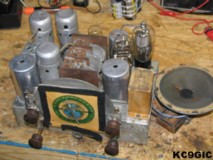
the chassis. The lower right photo shows the chassis
rewire and cleaning complete, along with a test speaker connected to
it. I had some matching tube shields that were
rescued from a Silvertone console years ago to replace the missing
ones. Cloth covered wire, available from Radio Daze, was used to replace
many of
the cut or missing wires. Below
Left: The chassis halfway cleaned and polished, Right: The completed
chassis.
Testing and
Troubleshooting
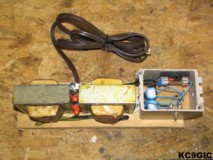
Before the radio could be tested, a power supply had to be built that could provide the 3 VDC for the A+ and 135 VDC for the C+. Two 1.5 VDC "D" cell batteries were used for the A+, and a homemade power supply for the B+. A simple design was used for a B+ power supply, very similar to the one on Phil's old radios, with a few modifications. The whole setup is powered off of a small isolation transformer using two 25.2 volt, 2 amp Stancor power transformers, and a fuse. This helps protect me and the radio. Below Center: The homebrew power supply.
Upon first powering up the radio, it did just as suspected, no sound, smoke, or any other signs of life. Troubleshooting started off by testing voltages on the tube pins and using the chart on the schematic as a guide. Everything looked good until I reached the 1C6 tube, which is used as a oscillator. Nothing on the plate, which is suppose to be 115 VDC. The missing voltage was traced back to a open coil, in the IF input transformer ( L6). An old IF transformer in my junk box was used as a replacement. After installing this, the voltage problem was fixed, but the receiver still made no sound. Something is not right here.... All of a sudden my brain kicked into gear, the IF frequency in this radio is 175 KC, and the replacement coil was 455 KC. I had the wrong coil! After smacking myself in the head, and a little bit of cursing, I proceeded to look for the correct replacement from a parts vendor.A replacement coil, # 30 tube, and the transformers for the power supply were purchased from Play Things of the Past.
After installing the correct coil, and aligning the receiver, it was working on both bands. There were still some minor problems, including bad connections on the band selector switch, and a bad connection somewhere that knocked out the entire AM band if the tuning condenser is moved at all.
Cabinet Restoration
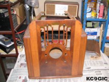
The cabinet had some obvious problems, mainly the top is disconnected with the rest of the cabinet. This is because all of the glue has dried up and the joints are all coming apart. The finish is not original, as mentioned before, so I did a few simple tests to see what it was. The usual tests for shellac and lacquer had no effect. Looked like I had a case of polyurethane here. Below: The cabinet before restoration.
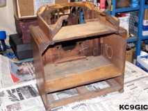
After a few weeks of re-gluing every piece of the cabinet using wood glue, C-clamps, and other clamps, the cabinet was ready to be stripped. I believe this radio was dipped long ago in some sort of stripper, since the glue had all been eaten away, and the veneer was cracked all over. A rather strong gel stripper was used to remove the poly, not letting it sit long enough to seep into the wood. The below photo shows the cabinet after stripping. The C-clamp is holding on some veneer that was falling apart on the grill. The lighter spots on the side are Minwax stainable wood filler used to fill in the cracks in the dried out veneer. Below center: The cabinet after being stripped and repaired.
Before the radio could be tested, a power supply had to be built that could provide the 3 VDC for the A+ and 135 VDC for the C+. Two 1.5 VDC "D" cell batteries were used for the A+, and a homemade power supply for the B+. A simple design was used for a B+ power supply, very similar to the one on Phil's old radios, with a few modifications. The whole setup is powered off of a small isolation transformer using two 25.2 volt, 2 amp Stancor power transformers, and a fuse. This helps protect me and the radio. Below Center: The homebrew power supply.
Upon first powering up the radio, it did just as suspected, no sound, smoke, or any other signs of life. Troubleshooting started off by testing voltages on the tube pins and using the chart on the schematic as a guide. Everything looked good until I reached the 1C6 tube, which is used as a oscillator. Nothing on the plate, which is suppose to be 115 VDC. The missing voltage was traced back to a open coil, in the IF input transformer ( L6). An old IF transformer in my junk box was used as a replacement. After installing this, the voltage problem was fixed, but the receiver still made no sound. Something is not right here.... All of a sudden my brain kicked into gear, the IF frequency in this radio is 175 KC, and the replacement coil was 455 KC. I had the wrong coil! After smacking myself in the head, and a little bit of cursing, I proceeded to look for the correct replacement from a parts vendor.A replacement coil, # 30 tube, and the transformers for the power supply were purchased from Play Things of the Past.
After installing the correct coil, and aligning the receiver, it was working on both bands. There were still some minor problems, including bad connections on the band selector switch, and a bad connection somewhere that knocked out the entire AM band if the tuning condenser is moved at all.
Cabinet Restoration
The cabinet had some obvious problems, mainly the top is disconnected with the rest of the cabinet. This is because all of the glue has dried up and the joints are all coming apart. The finish is not original, as mentioned before, so I did a few simple tests to see what it was. The usual tests for shellac and lacquer had no effect. Looked like I had a case of polyurethane here. Below: The cabinet before restoration.
After a few weeks of re-gluing every piece of the cabinet using wood glue, C-clamps, and other clamps, the cabinet was ready to be stripped. I believe this radio was dipped long ago in some sort of stripper, since the glue had all been eaten away, and the veneer was cracked all over. A rather strong gel stripper was used to remove the poly, not letting it sit long enough to seep into the wood. The below photo shows the cabinet after stripping. The C-clamp is holding on some veneer that was falling apart on the grill. The lighter spots on the side are Minwax stainable wood filler used to fill in the cracks in the dried out veneer. Below center: The cabinet after being stripped and repaired.
After
the Minwax wood filler had dried, it was sanded down with 400 grit
sandpaper. The cabinet was then wiped down with mineral spirits, and a
tack cloth was used to remove any dust. A few coats of Minwax brand
sealer were then applied. 24 hours after this dried, the cabinet was
sprayed with Van Dyke Brown colored Mohawk toner. Since this was my
first cabinet restore using this method, much care was used with the
application. Even with my best efforts, the cabinet still developed
some bad runs and other blemishes. The only option was to strip it with
lacquer
thinner and start over.
My second try with the toner was much better. The final coats of lacquer were Deft brand clear gloss. After this had dried, the cabinet was lightly sanded with 800 grit wet/dry sandpaper to achieve a very smooth finish. It was then buffed by hand with a automotive wax to get a nice shine.
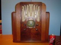
The original grill cloth and board that it was mounted to were long gone. A replacement cloth was purchased from RadioDaze, and a new board was made from the thick cardboard in the cover of a old three ring binder. Below Center, The photo used in the auction.
Back
to
CollectionMy second try with the toner was much better. The final coats of lacquer were Deft brand clear gloss. After this had dried, the cabinet was lightly sanded with 800 grit wet/dry sandpaper to achieve a very smooth finish. It was then buffed by hand with a automotive wax to get a nice shine.
The original grill cloth and board that it was mounted to were long gone. A replacement cloth was purchased from RadioDaze, and a new board was made from the thick cardboard in the cover of a old three ring binder. Below Center, The photo used in the auction.
Back to Homepage
© Copyright 2005 "Jeremy's Antique Radios"