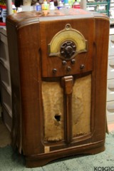
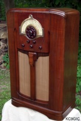
"Before" "After"
Brand: Westinghouse Electric Corp. Year of Manufacture: 1937 Frequency Range(s): 540 - 1800KC, 1.8 - 5.5MC, 6 - 18MC
Tube Lineup: 5X4G Rectifier, (2X) 6V6G PP Output, 6C5 P.Inv., 6Q7 2nd Det/A.V.C., 6K7 A.F.C./Discim., 6K7 R.F. Amp
Tube Lineup: 6J7 A.F.C. Control, 6H6 Discriminator Rectifier, 6K7 I.F. Amp, 6A8 1st Det/Osc., 6U5 Tuning Eye
Schematic: Available here, courtesy of Nostalgia Air. Riders 12-13
Tube Lineup: 5X4G Rectifier, (2X) 6V6G PP Output, 6C5 P.Inv., 6Q7 2nd Det/A.V.C., 6K7 A.F.C./Discim., 6K7 R.F. Amp
Tube Lineup: 6J7 A.F.C. Control, 6H6 Discriminator Rectifier, 6K7 I.F. Amp, 6A8 1st Det/Osc., 6U5 Tuning Eye
Schematic: Available here, courtesy of Nostalgia Air. Riders 12-13
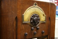
May of 2009, in route to Kokomo, IN on a three hour trip to the Indiana Historical Radio Society spring meet. I recall thinking to myself on the drive up that I had a fool-proof plan on how to avoid hauling home any large radios or consoles. I would make sure to leave my truck at home and drive my car. That way I physically had no room to haul anything home! As I would find out, like many well thought out plans in history, this one was destined for failure.
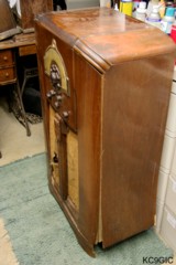
This miserable looking radio was propped up in the corner of the convention center room, next to the silent auction tables. It was attracting a great deal of attention from fellow club members and restorers. Not because of the miserable condition or low price, but because of the high tube count, well built chassis with triple tuned IF, and the overall rarity of this radio. While many seemed to be impressed by this beast, no one was stepping forward to take it home. The radio was complete, but in several pieces, with several parts being damaged. To summarize the eventual outcome, this radio just barely fit in the back seat of my girlfriend's Chevy Impala! Below photos: The Westinghouse as purchased, before restoration was began.
The
restoration
of the electronics on this radio began with a twist,
but ended up being nothing more than routine later on. After a good
cleaning of dust and loose debris from the chassis, the first repairs
included replacing the filter capacitors and installing a new power
cord, which I opted to use reproduction cloth-covered cord. On the
first power up, I was greeting by a 60 cycle hum, and the B+ voltages
were way off. As some point in time, the power transformer had been
replaced, and it was a sloppy job at that. Many other capacitors,
controls, and resistors had also been replaced over time. With a
schematic in hand, I was quick to notice that the center tap on the
power transformer was not connected to the proper place. The way
everything was connected, the filter capacitors were essentially doing
nothing at all!
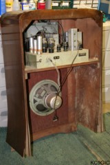
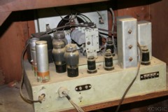
With the nasty looking repairs of the past, I decided to clean the wiring up and check out the rest of the power supply section. On the second power up, the hum was gone, but after several seconds of warming up, the ammeter on my power supply would begin to jump around. That is when I noticed arcing inside one of the 6V6 power output tubes. Testing both of the 6V6's on my B7K 747B tube tester revealed shorts in both of them. Further testing of tubes revealed three more with internal shorts, and the 6C5 inverter showing no grid emissions. All of the tubes in this radio were RCA branded with matching date codes. The large number of bad tubes seemed rather odd to me, the most that I have ever encountered in a radio. The mis-wired CT of the transformer must have been the cause. It had been connected to a point that shared a connection with the cathodes of the 6V6 tubes. Perhaps this created some kind of crazy voltages inside of the tubes, thus causing arcing and eventual shorts.
With the replacement of the bad tubes, on the third power up the receiver was working much better. The paper capacitors were then replaced, testing out the receiver after replacing two or three at a time. This way if I make a mistake, it is much easier to retrace my work and find the problem. Once the capacitors had all been replaced, the controls were cleaned and the alignment was checked. The resistor in the eye tube base was way out of tolerance, so it was also replaced. Two small modifications were then made to the radio circuitry. A fuse was added to the hot side of the AC line voltage going to the primary of the power transformer. I also added a thermistor on the 120V AC. The thermistor is around 200Ω when cold, and once warmed up, drops to just a few ohms. With the addition of the thermistor, this supposedly decreases "thermal impact" of the tube filaments and other components by letting the voltage slowly rise. Another result of using a thermistor is that it knocks down the AC line voltage by a few volts, effectively causing the power transformer to run a little cooler.
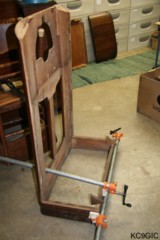
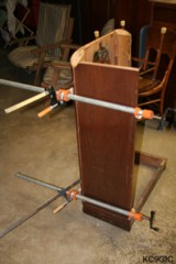
As you can see in the above photos from before the restoration, the cabinet was in several pieces and needed quite a few repairs. Luckily, all of the pieces were accounted for, including some of the larger veneer chips. The cabinet restoration began by disassembling the remainder of the cabinet, and building it up from there. The sides, with a top layer of veneer and several sandwiched layers of a cheaper wood, had to be completely re-glued. The base was reattached/ glued to the front panel. The repaired sides were then attached, followed by the top. Below photos: the cabinet during reassembly
With the nasty looking repairs of the past, I decided to clean the wiring up and check out the rest of the power supply section. On the second power up, the hum was gone, but after several seconds of warming up, the ammeter on my power supply would begin to jump around. That is when I noticed arcing inside one of the 6V6 power output tubes. Testing both of the 6V6's on my B7K 747B tube tester revealed shorts in both of them. Further testing of tubes revealed three more with internal shorts, and the 6C5 inverter showing no grid emissions. All of the tubes in this radio were RCA branded with matching date codes. The large number of bad tubes seemed rather odd to me, the most that I have ever encountered in a radio. The mis-wired CT of the transformer must have been the cause. It had been connected to a point that shared a connection with the cathodes of the 6V6 tubes. Perhaps this created some kind of crazy voltages inside of the tubes, thus causing arcing and eventual shorts.
With the replacement of the bad tubes, on the third power up the receiver was working much better. The paper capacitors were then replaced, testing out the receiver after replacing two or three at a time. This way if I make a mistake, it is much easier to retrace my work and find the problem. Once the capacitors had all been replaced, the controls were cleaned and the alignment was checked. The resistor in the eye tube base was way out of tolerance, so it was also replaced. Two small modifications were then made to the radio circuitry. A fuse was added to the hot side of the AC line voltage going to the primary of the power transformer. I also added a thermistor on the 120V AC. The thermistor is around 200Ω when cold, and once warmed up, drops to just a few ohms. With the addition of the thermistor, this supposedly decreases "thermal impact" of the tube filaments and other components by letting the voltage slowly rise. Another result of using a thermistor is that it knocks down the AC line voltage by a few volts, effectively causing the power transformer to run a little cooler.
As you can see in the above photos from before the restoration, the cabinet was in several pieces and needed quite a few repairs. Luckily, all of the pieces were accounted for, including some of the larger veneer chips. The cabinet restoration began by disassembling the remainder of the cabinet, and building it up from there. The sides, with a top layer of veneer and several sandwiched layers of a cheaper wood, had to be completely re-glued. The base was reattached/ glued to the front panel. The repaired sides were then attached, followed by the top. Below photos: the cabinet during reassembly
There
were several veneer repairs needed, mainly on the curved section
where the top meets the front panel. Due to the cabinet falling apart,
there was a large crack present here. A combination of some veneer and
stain-able wood filler was used to patch the various small chips and
cracks in the veneer. I like to preserve the original finish if
possible on a radio, but I had my doubts on this one. I used some
mineral spirits and a scrubbing pad to clean up the cabinet once
everything was glued back together and all other repairs were made. The
cleaned cabinet looked rather promising, so I decided to try my method
to touch up the old finish.
To blend in the chips/scratches/ bad spots in general, I wiped the entire cabinet down with "Special Walnut" colored stain. This was followed by wiping the cabinet off with a clean rag to remove the excess stain. The result of this looked very good. A few of the repaired areas required some additional touch-up using various colors of Minwax stain sticks. After the stain had dried overnight, it was time for some new lacquer. The entire cabinet was wiped down with a tack cloth, and final touch ups with the stain sticks were performed. Using a "Critter" spray gun, I then coated the cabinet with several layers of thinned gloss lacquer. The cabinet was wet-sanded in between coats with 400 grit wet/dry sandpaper. The final coat of lacquer looks pretty good to me, so I didn't both rubbing it out or anything.
The final repairs included replacing the grill cloth, patching the hole in the tuning knob, and making a new dial cover. The knobs were all polished using some brown shoe polish.
Due to a very busy college semester, this project was drawn out over many months. It did however prove to be a good stress relieving pastime, a way for me to escape life for a while and work at the bench. I am very impressed with the performance of this receiver. The push-pull 6V6s deliver a powerful 10 watts of undistorted audio, along with a very selective tuning to make with is great DXer. With the initial purchase price and restoration costs, I probably have less than $100 invested in this radio. That's a darn good price for a fully restored twelve tube Westinghouse! This one ranks high up in my list of great looking and performing radios, and will maintain a proud position in my radio room for years to come.