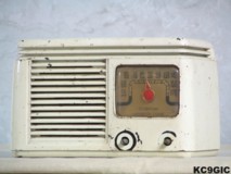
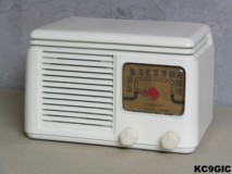
Before After
Brand: John Meck Industries Inc.. Year Of Manufacture: 1948 Frequency Range: 550 - 1700KC
Tube
lineup: 35Z5 Rectifier, 50L6 GT Output, 12SQ7, 12SG7
Schematic: Available here, courtesy of Nostalgia Air. Riders 22-1
Schematic: Available here, courtesy of Nostalgia Air. Riders 22-1
This radio, and a RCA 8X542, were high school graduation gifts in June of 2004. This radio was made in Plymouth, Indiana by John Meck Industries, Inc. Other than the paper label on the bottom, the only other markings on the radio are "Custom, Mirror - Tone", which is located on the dial. Some research revealed that this was a somewhat unknown manufacture that made cheap radios. The quality of the radio supports that information. It looks like they used whatever parts they had laying around, thus several of the component values were way off from the schematic values. This radio also uses what looks like a TRF ( tuned radio frequency ) type receiver, instead of the more common superheterodyne type.
Electronic Restoration
This radio received the usual treatment when repairing the electronics. All paper and electrolytic capacitors were replaced. A new brown power cord was also installed and the switch and volume control were cleaned/lubricated. The old dust on the chassis was removed with a vacuum cleaner and a paintbrush. This radio uses the chassis as a common connection in the circuit, so depending on which way the power cord is plugged into a receptacle, the chassis could be hot with 120 volts AC. To prevent a potential deadly shock to me or my test equipment while working on this radio, an isolation transformer will be used along with a variac to test the radio.
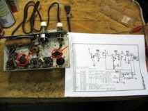
When first powered up, the radio wasn't making any sounds at all, the tubes were not even lighting up. While testing the tubes, a 12SG7 was found to have an open filament, and the 35Z5 GT had an internal short. After replacing these tubes, the radio was making a few sounds, and a few weak stations could be heard. Something had to be wrong. After doing some research, what looked like the usual mica capacitors, which rarely go bad, were really paper types stuffed into the same shells. Below center: The deceiving capacitors circled in red.
After
replacing the remaining capacitors the radio was receiving
several stations with a long wire antenna attached. With a few minor
adjustment to the two trimmer capacitors located on the tuning
cap, a few strong local stations could be picked up.
Cabinet Restoration
As you can see in the "before" photo, the cabinet needed some work. First thing on the list was a good cleaning with some soapy water, taking care to mask off the paper label on the bottom. This made the cabinet look a little better, but there were still many, many paint chips. Since this radio was not very valuable, a repainting was in order.
Some 3M brand, 400 grit wet/dry sandpaper was used to smooth out the paint chips. The cabinet was then wiped down with mineral spirits to remove any dirt or grease. Three light coats of Rust-Oleum brand gray primer was sprayed on as a base coat. Waiting 24 hours after this dried, the cabinet was once again sanded, but with 800 grit wet/dry sandpaper. The final step before the paint would be sprayed on was a cleaning with a sticky tack cloth to remove dust and particles. Ivory gloss colored Krylon brand spray paint was used for the final three light coats. After this had dried, a few coats of clear gloss lacquer were sprayed on. The end result doesn't look perfect, but it looks pretty good for my first cabinet repainting.
Finding a pair of knobs for this radio would prove to be challenging. When searching online for a photo of this model, I came across an article on the rec.antiques.radio+phono newsgroup from 2001, where the repairman mentioned working on this model. I threw him some email, and received a reply from him with a photo of his radio with the original knobs and a sketch of the back ( Thanks Ed, aka: Blacksmith! ). After posting a few want adds online, some knobs were tracked down ( Thanks Mike!). With the knobs out of the way, I could focus on the missing back. Using some 1/8" thick Masonite type board from a local hardware store, a replacement was recreated diagram that Ed had supplied. The plastic dial cover only required some cleaning with Novus brand polishes to have it shinning again.