"Before" "After"
Brand: Philco Radio &
Telev. Corp. Year
Of Manufacture: 1938
Frequency Range(s): 530 to 1600 K.C., 1.58 to 4.75 M.C., 4.7 to 7.4 M.C., 7.35 to 11.6 M.C., 11.5 to 18.2 M.C.
Tube lineup: 5X4G Rectifier, 6L6G X2 Push/Pull Output, 6J5G Driver, 6U7G R.F., 6A8G Mixer, 6A8G Osc.,
-Cont: 6N7G Osc. Control, 6J5G X2 Discriminator, 6R7G 1st. Audio, 6K7G 2nd Det/Mag-Tun, 6J5G AVC,
-Cont: 6K7G 2nd I.F., 6K7G 1st I.F.
Schematic: Available here, courtesy of Nostalgia Air. Riders 8-80
Project Beginings
In February of 2006, Philco expert Ron Ramirez was selling several radios on eBay. Since he only live an hour away from me, I figured I could buy a few and save on the shipping cost by picking them up in person. I wasn't quite sure why I bid on this one. Per the auction, this radio needed allot of work to piece it back together. Many of the radios Ron was selling were pretty close to being parts radios only, one I ended up winning, a Philco 3118B, had been parted out already.
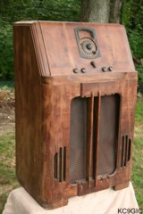
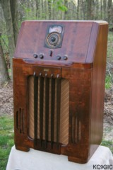
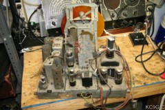
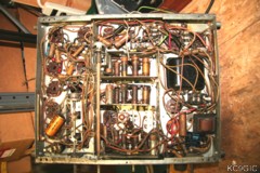
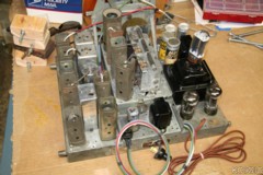
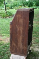
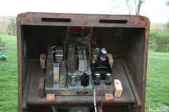
So on a miserable cloudy and cold day I made to trek to Evansville to pick up this beast. Naturally a blizzard blows in when I start heading back, a good test for the new set of all-terrain tires I had recently put on my Ranger. Long story short, I made it back and packed this beast down to my basement storage area on my own (this radio is heavy!). At the time I did a little bit of preliminary work, mainly getting a list together of missing parts. Other than being moved from one side of storage to the other, this radio would sit patiently until fall of 2008 when restoration would begin. Below photos: The cabinet and chassis prior to restoration in August 2008.
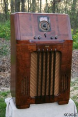
About the 38-116
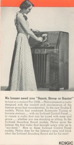
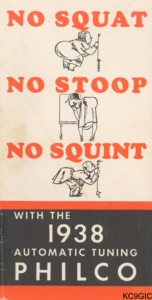
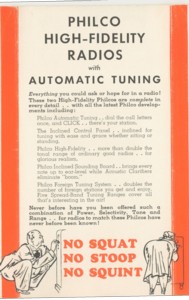
The 38-116 is one of Philco's "No Squat, No Stoop, No Squint" line of radios, with around 25,600* manufactured.. The whole idea behind that slogan was the slanted or inclined control panel and dial. It made it easier for a person to see the dial, without bending over or squatting down. According to Philco Radio 1928-1942 by Ron Ramirez (Yes, the same guy I bought my 38-116 from!), this advertising campaign was targeted for women. The 1938 dealer catalog states, " Here is a radio that a woman can tune with ease and grace...." Hey, the Great Depression is going on, whatever works to sell a few more radios! Selling at $200 new, not allot of families could afford one of these. Below: Original Philco advertisements for the 38-116 and the 1938 model year.
This model and others from the 1938 year featured an Automatic Tuning Mechanism. This consisted of a large round dial with a tuning knob on the edge of the dial. To tune a station, you simply grasp the knob and turn the dial around until it stops. The dial stops because there are up to fifteen selector stops on the mechanism. Other features were three acoustic clarifiers, which are called passive radiators in todays terms. These are basically speakers without voice coils or magnets, and were meant to "assist" the main speaker during operation. A monster chassis that utilizes 15 power hungry tubes, a power output of 15 watts, and receiving 5 bands make up this beast of a radio. Truly a stunning example of a technological achievement of its time.
Any observant repairman will quickly notice that there are two different schematics for this model, a 38-116 code 121 and a 38-116 code 125. The main difference I can find is a change in the tube lineup. This being the mixer tube was changed from a 6L7G in the 121 to a 6A8G in the 125, and the RF tube being changed from a 6K7G in the 121 to a 6U7G in the 125. My radio is a code 125.
* Statistics from Philco Radio 1928-1942 by Ron Ramirez.
Electronic Restoration
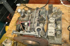
No project is more in intimidating that a 15 tube chassis that has been hacked up by a previous repairman of the past. Before I purchased this radio, Ron had started piecing it back together, a tough task for one to undertake. Perhaps that is why I put off restoring this radio for almost three years. My first job was to begin tracking down missing or damaged parts. Original replacement parts that had to be found included:
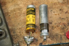
With many of the new parts on hand or on order, it was time to dig into the chassis. A vacuum and a paintbrush were used to rid the chassis of dirt and debris. The dial assembly was then removed, taking many photos and organizing all of the parts in little plastic bags. With a schematic on hand, work was started in the power supply section, removing the old repairs and installing new electrolytic (filters) and paper capacitors. The old paper capacitors were heated and gutted. Modern replacement capacitors were then sealed inside the shells of the originals, thus preserving the look of the chassis. The new electrolytics were installed and left hanging where the original surface mounted can capacitors once were. This was just temporary until the replacement (old) can capacitors arrived and could be gutted with the new electrolytics installed inside. Below Left: The later type filter capacitors where the originals once were, Center: The bottom of the chassis before recapping, Right: The original style filters being "gutted" so that modern replacements can be installed inside and concealed.
Much of the original wiring also had to be replaced. While the cloth covered wire in radio of this vintage usually holds together pretty good, it will easy crumble if flexed too much. The wiring harness going to the speaker had to be replaced. Modern cloth covered wire rated for 600V was used for this, keeping the colors the same as the original if possible. Other wires needing to be replaced included all of those going to tube grid caps, feeding the pilot lamps on the dial, and the wiring harness going to the two switches on the Automatic Tuning Mechanism. Once this was replaced, and a new reproduction cloth covered cord was installed, it was time to prepare for powering up the radio. Below Photo: The radio prior to testing, notice the speaker clamped together, the glue holding the cone to the frame had dried up requiring to it be fixed.
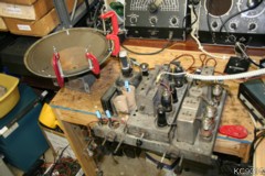
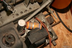
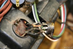
Once everything was put together and the speaker was reglued, my radio was carefully powered up using a isolation/variac power supply and carefully observing the amperage draw. The radio was showing signs of life, receiving stations on most bands. There still were a few nagging problems, like intermittent shorts causes by bad wire insulation and corroded connections on the band selector switch. One problem in particular was sparking and a loose connection inside of the rectifier tube socket, mounted on top of the power transformer. in the past someone rewired the socket so that a 5U4 could be used as a rectifier. The 5U4 is an acceptable replacement for the 5X4, but the 5U4 uses a different pin configuration . Fixing this problem required the use of some heat shrink tuning to keep the sharply bent wires inside from shorting out, as the original insulation was falling apart. Below Photo: The socket and wiring prior to being repaired.
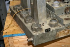
At this point the radio was working extremely well despite its history of rough repairs. Apparently the only thing someone hadn't messed with in the past were the trimmer capacitors, as no alignment was needed. At this point to was time to get the chassis looking better cosmetically. Some NOS tube shield bases were acquired to replace those that had been hacked up. The rivets holding down the originals had to be drilled out, and flathead 6-32 screwed and nuts were used to bolt in the replacements. The black paint on the transformers was chipped up, so a new coat of black lacquer as sprayed on to spruce them up a bit. Finally using a Dremel and a wire brush the entire chassis was lightly cleaned, using Brasso on some parts. The final results don't look too bad for a seventy year old piece of metal. Below Photos: The reassembled and completed chassis, minus some polishing on the tube shields.
Cabinet Restoration
The cabinet had been stripped in the past, but there were some kind of run marks all over it. A liquid had been splashed on the sides and top, resulting in big bleached looking spots. My largest concern was if these spots could be removed or covered up. Washing and scrubbing with different chemicals had no effect. Some orange Citistrip stripper was brushed on over the spots, and was allowed to soak in for half an hour or so. Once the stripper was removed, and the cabinet was washed down, the spots seemed to be completely gone. Below photo: The cabinet before being cleaned showing the run marks.
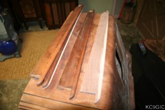
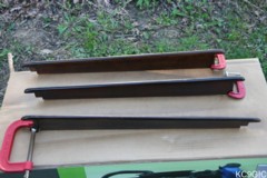
The other obstacle on restorignt he cabinet was replacing the two missing vertical bars in front of the speaker grille. A close family friend who restores antique furniture knew of an Amish woodworker who could reproduce about any obscure part as long as he had a pattern to go by. So they took one of the remaining bars to him, and a few weeks later I had two perfect reproductions. As for a price, the woodworker wouldn't accept more than $10 for the job. All of the bars were sanded and the grain was filled. They were then toned with Mohawk extra dark walnut and then medium brown walnut so that they would match. Below Left: The new and original bars next to each other, Right: Being toned to match each other.
In February of 2006, Philco expert Ron Ramirez was selling several radios on eBay. Since he only live an hour away from me, I figured I could buy a few and save on the shipping cost by picking them up in person. I wasn't quite sure why I bid on this one. Per the auction, this radio needed allot of work to piece it back together. Many of the radios Ron was selling were pretty close to being parts radios only, one I ended up winning, a Philco 3118B, had been parted out already.
So on a miserable cloudy and cold day I made to trek to Evansville to pick up this beast. Naturally a blizzard blows in when I start heading back, a good test for the new set of all-terrain tires I had recently put on my Ranger. Long story short, I made it back and packed this beast down to my basement storage area on my own (this radio is heavy!). At the time I did a little bit of preliminary work, mainly getting a list together of missing parts. Other than being moved from one side of storage to the other, this radio would sit patiently until fall of 2008 when restoration would begin. Below photos: The cabinet and chassis prior to restoration in August 2008.
About the 38-116
The 38-116 is one of Philco's "No Squat, No Stoop, No Squint" line of radios, with around 25,600* manufactured.. The whole idea behind that slogan was the slanted or inclined control panel and dial. It made it easier for a person to see the dial, without bending over or squatting down. According to Philco Radio 1928-1942 by Ron Ramirez (Yes, the same guy I bought my 38-116 from!), this advertising campaign was targeted for women. The 1938 dealer catalog states, " Here is a radio that a woman can tune with ease and grace...." Hey, the Great Depression is going on, whatever works to sell a few more radios! Selling at $200 new, not allot of families could afford one of these. Below: Original Philco advertisements for the 38-116 and the 1938 model year.
This model and others from the 1938 year featured an Automatic Tuning Mechanism. This consisted of a large round dial with a tuning knob on the edge of the dial. To tune a station, you simply grasp the knob and turn the dial around until it stops. The dial stops because there are up to fifteen selector stops on the mechanism. Other features were three acoustic clarifiers, which are called passive radiators in todays terms. These are basically speakers without voice coils or magnets, and were meant to "assist" the main speaker during operation. A monster chassis that utilizes 15 power hungry tubes, a power output of 15 watts, and receiving 5 bands make up this beast of a radio. Truly a stunning example of a technological achievement of its time.
Any observant repairman will quickly notice that there are two different schematics for this model, a 38-116 code 121 and a 38-116 code 125. The main difference I can find is a change in the tube lineup. This being the mixer tube was changed from a 6L7G in the 121 to a 6A8G in the 125, and the RF tube being changed from a 6K7G in the 121 to a 6U7G in the 125. My radio is a code 125.
* Statistics from Philco Radio 1928-1942 by Ron Ramirez.
Electronic Restoration
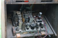
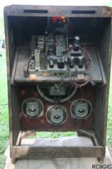
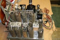
No project is more in intimidating that a 15 tube chassis that has been hacked up by a previous repairman of the past. Before I purchased this radio, Ron had started piecing it back together, a tough task for one to undertake. Perhaps that is why I put off restoring this radio for almost three years. My first job was to begin tracking down missing or damaged parts. Original replacement parts that had to be found included:
- 5 Tube Shield Bases,
someone had hacked up the originals to accept metal or GT style tubes.
- 4 New filter cans and mounting brackets to restuff, the originals were completely removed.
- A five pin plug and socket for the speaker, these had been replaced with a Molex type plug and socket.
- Several tube shields, these were missing.
- A complete set of G style tubes, just wanted the chassis to look good and original after restoration.
- 2 new tube grid caps, two were replaced with some big gawdy black plastic ones.
- A new dial scale, the one with my chassis had been broken and I would later find out was the wrong one entirely.
Several
sources were used to find these parts. Most were purchased from Mark Oppat's Old Radio Parts,
Gary at Play Things of Past,
with quite a few other parts being purchased via a wanted ad on the Antique Radio Forums
classified section.
Radio and test equipment guru Alan Douglas was able to supply me with
many "G" style tubes for this radio. Below photos:
The chassis when first removed from the cabinet, showing an extent of
the needed repairs.- 4 New filter cans and mounting brackets to restuff, the originals were completely removed.
- A five pin plug and socket for the speaker, these had been replaced with a Molex type plug and socket.
- Several tube shields, these were missing.
- A complete set of G style tubes, just wanted the chassis to look good and original after restoration.
- 2 new tube grid caps, two were replaced with some big gawdy black plastic ones.
- A new dial scale, the one with my chassis had been broken and I would later find out was the wrong one entirely.
With many of the new parts on hand or on order, it was time to dig into the chassis. A vacuum and a paintbrush were used to rid the chassis of dirt and debris. The dial assembly was then removed, taking many photos and organizing all of the parts in little plastic bags. With a schematic on hand, work was started in the power supply section, removing the old repairs and installing new electrolytic (filters) and paper capacitors. The old paper capacitors were heated and gutted. Modern replacement capacitors were then sealed inside the shells of the originals, thus preserving the look of the chassis. The new electrolytics were installed and left hanging where the original surface mounted can capacitors once were. This was just temporary until the replacement (old) can capacitors arrived and could be gutted with the new electrolytics installed inside. Below Left: The later type filter capacitors where the originals once were, Center: The bottom of the chassis before recapping, Right: The original style filters being "gutted" so that modern replacements can be installed inside and concealed.
Much of the original wiring also had to be replaced. While the cloth covered wire in radio of this vintage usually holds together pretty good, it will easy crumble if flexed too much. The wiring harness going to the speaker had to be replaced. Modern cloth covered wire rated for 600V was used for this, keeping the colors the same as the original if possible. Other wires needing to be replaced included all of those going to tube grid caps, feeding the pilot lamps on the dial, and the wiring harness going to the two switches on the Automatic Tuning Mechanism. Once this was replaced, and a new reproduction cloth covered cord was installed, it was time to prepare for powering up the radio. Below Photo: The radio prior to testing, notice the speaker clamped together, the glue holding the cone to the frame had dried up requiring to it be fixed.
Once everything was put together and the speaker was reglued, my radio was carefully powered up using a isolation/variac power supply and carefully observing the amperage draw. The radio was showing signs of life, receiving stations on most bands. There still were a few nagging problems, like intermittent shorts causes by bad wire insulation and corroded connections on the band selector switch. One problem in particular was sparking and a loose connection inside of the rectifier tube socket, mounted on top of the power transformer. in the past someone rewired the socket so that a 5U4 could be used as a rectifier. The 5U4 is an acceptable replacement for the 5X4, but the 5U4 uses a different pin configuration . Fixing this problem required the use of some heat shrink tuning to keep the sharply bent wires inside from shorting out, as the original insulation was falling apart. Below Photo: The socket and wiring prior to being repaired.
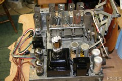
At this point the radio was working extremely well despite its history of rough repairs. Apparently the only thing someone hadn't messed with in the past were the trimmer capacitors, as no alignment was needed. At this point to was time to get the chassis looking better cosmetically. Some NOS tube shield bases were acquired to replace those that had been hacked up. The rivets holding down the originals had to be drilled out, and flathead 6-32 screwed and nuts were used to bolt in the replacements. The black paint on the transformers was chipped up, so a new coat of black lacquer as sprayed on to spruce them up a bit. Finally using a Dremel and a wire brush the entire chassis was lightly cleaned, using Brasso on some parts. The final results don't look too bad for a seventy year old piece of metal. Below Photos: The reassembled and completed chassis, minus some polishing on the tube shields.
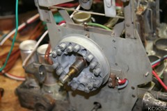
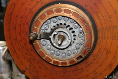
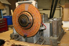
There is a certain
procedure that has to be followed when disassembling the automatic
tuning mechanism, which is detailed in the Philco Service Bulletin no.
273. The bulletin, along with a wealth of other hard-to-find
information can be purchased from The Philco
Repair Bench. The entire tuning mechanism was disassembled,
cleaned, and rewired. The
last repair to the chassis was the replacement of the dial scale. The
original wasn't in bad shape when I started restoration. During the
process through the delicate dial scale was cracked. A replacement dial
scale was purchased from Mark Oppat's Old Radio Parts.
Mark manufactures near perfect reproductions of many dials, including
one for my 38-116. While comparing the original dial to the
reproduction, I noticed a difference in the frequencies. Doing
some searching online, Ron Ramirez made a post on the Philco
Phorums back in 2005 talking about this very radio. He
mentions that he had to replace the entire automatic tuning
mechanism.....Thats it! Researching the part number of my
original dial, I found out it is a dial for a 37-116 model that
has different circuitry, thus why the frequencies on the new correct
dial didn't match up entirely. Below
Left: The automatic tuner disassembled, Center: The original dial
scale, Right: The reassembled tuner with the reproduction dial
scale.
Cabinet Restoration
The cabinet had been stripped in the past, but there were some kind of run marks all over it. A liquid had been splashed on the sides and top, resulting in big bleached looking spots. My largest concern was if these spots could be removed or covered up. Washing and scrubbing with different chemicals had no effect. Some orange Citistrip stripper was brushed on over the spots, and was allowed to soak in for half an hour or so. Once the stripper was removed, and the cabinet was washed down, the spots seemed to be completely gone. Below photo: The cabinet before being cleaned showing the run marks.
The other obstacle on restorignt he cabinet was replacing the two missing vertical bars in front of the speaker grille. A close family friend who restores antique furniture knew of an Amish woodworker who could reproduce about any obscure part as long as he had a pattern to go by. So they took one of the remaining bars to him, and a few weeks later I had two perfect reproductions. As for a price, the woodworker wouldn't accept more than $10 for the job. All of the bars were sanded and the grain was filled. They were then toned with Mohawk extra dark walnut and then medium brown walnut so that they would match. Below Left: The new and original bars next to each other, Right: Being toned to match each other.
The bars were then reglued to the cabinet.
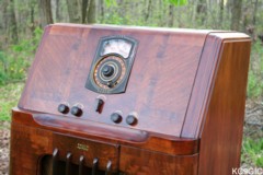
With no other repairs needed, it was time to refinish the cabinet. The
whole cabinet was sanded prior to refinished, and any dust was blown
away with an air compressor followed by wiping down with a tack cloth.
Deft brand gloss lacquer was used, sprayed on with a Critter spray gun.
The lacquer was thinned down, using three parts lacquer and one part
thinner. After several coats of lacquer, the decals were ready to be
installed. All of the decals needed for this model were purchased from RadioDaze. These decals were a royal PITA to apply! There is a word in
the shape of an arc over each knob that designates the function of that
particular control. These were very hard to match up and keep a
consistent distance between them all. Applying these was a tedious
process, but the final result turned out pretty good. Once the decals
had dried, a layer of clear lacquer was sprayed one over them.
Originally this radio used a "V" pattern grille cloth. This was long gone on my radio, and replaced by something that almost resembled a plastic mesh. A reproduction cloth was also purchased from RadioDaze. Pattern # 41, Chevron "V", was used, the same type as the original. The grille cloth would also prove to be a royal PITA to install. If the cloth was slightly off centered of warped, it would be very obvious with the vertical bars in front of it. After several tries, I was able to get the cloth positioned so that it was pretty close, but it was still slightly off in places. Messing with the cloth too much would risk damaging it.
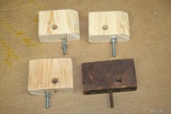
At this point it was time for complete reassembly. This radio uses a odd method to hold down the chassis. The chassis has four pins on each end of the sides that fit into a wooden block. The wooden block has a carriage bolt that goes through the mounting board that the chassis sits on, and a nut is tightened below. Three out of my four mounts were gone. Replacements we made using 2X4 lumber and 1/4" carriage bolts. Below photo: the replacement mounts.
Final Results
I am quite satisfied with the outcome of this restoration. I have always wanted a high end radio for my collection, but never wanted to pay the high price as these sometime command. When all said and done, I have around $200-$300 invested in this project. A very reasonable amount to me, and the final results were definitely worth the money and efforts. There are still a few minor flaws that need to be fixed, such as finding a replacement back panel. But until then, this radio is pretty much complete.
Originally this radio used a "V" pattern grille cloth. This was long gone on my radio, and replaced by something that almost resembled a plastic mesh. A reproduction cloth was also purchased from RadioDaze. Pattern # 41, Chevron "V", was used, the same type as the original. The grille cloth would also prove to be a royal PITA to install. If the cloth was slightly off centered of warped, it would be very obvious with the vertical bars in front of it. After several tries, I was able to get the cloth positioned so that it was pretty close, but it was still slightly off in places. Messing with the cloth too much would risk damaging it.
At this point it was time for complete reassembly. This radio uses a odd method to hold down the chassis. The chassis has four pins on each end of the sides that fit into a wooden block. The wooden block has a carriage bolt that goes through the mounting board that the chassis sits on, and a nut is tightened below. Three out of my four mounts were gone. Replacements we made using 2X4 lumber and 1/4" carriage bolts. Below photo: the replacement mounts.
Final Results
I am quite satisfied with the outcome of this restoration. I have always wanted a high end radio for my collection, but never wanted to pay the high price as these sometime command. When all said and done, I have around $200-$300 invested in this project. A very reasonable amount to me, and the final results were definitely worth the money and efforts. There are still a few minor flaws that need to be fixed, such as finding a replacement back panel. But until then, this radio is pretty much complete.